Visualizing seismic data on a random line
You can use a random cross section to visualize your seismic data in the Seismic View or 3D View. Where 'standard' seismic sections (Inlines, Crosslines, Depth/Timeslices) have dedicated directions, a random section enables you to display seismic data along any direction for optimal QC across stratigraphic or structural features, or well groups. Via stair-step snapping, JewelSuite snaps the random cross section to the center of the intersected seismic voxet cells and creates an internal stair-step cross section (see image below). As a result, original seismic trace data is displayed in the Seismic View without interpolation.
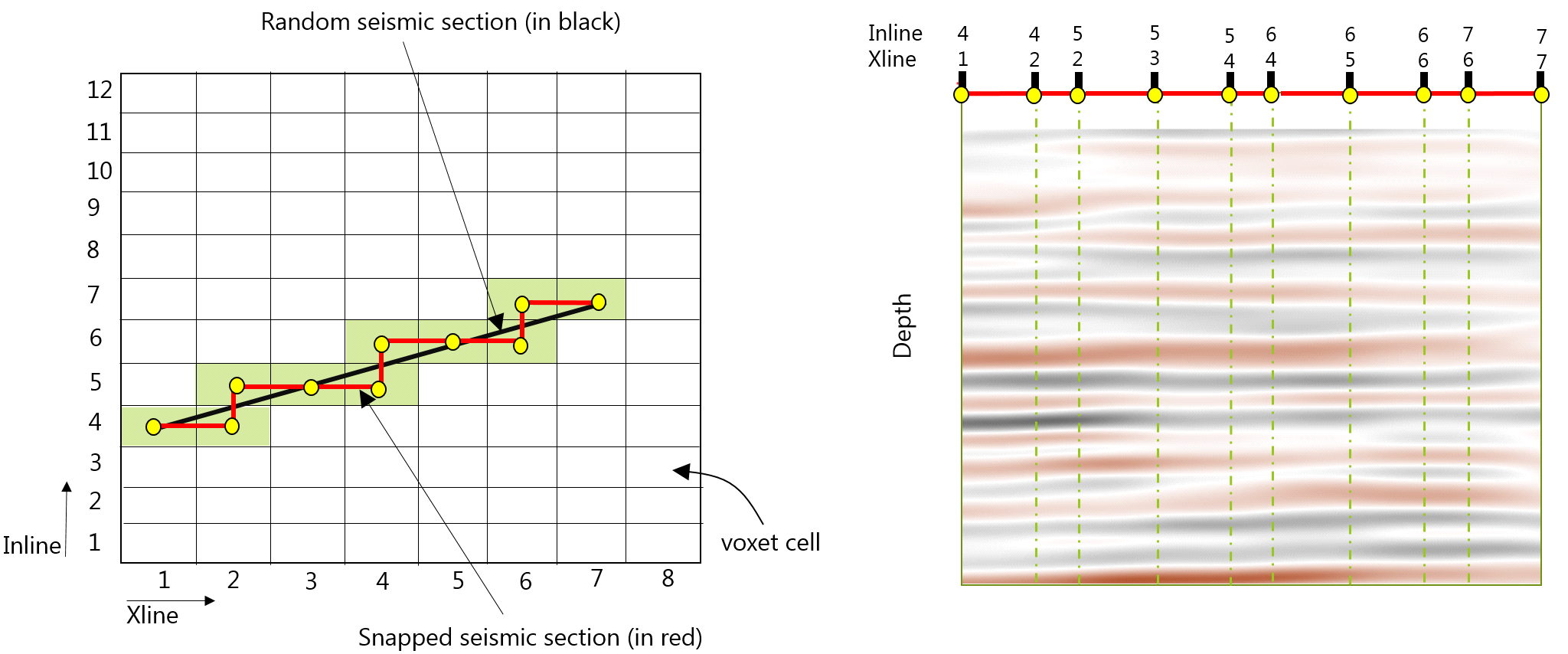
Schematic illustration of stair-step snapping. Left image (top view): to display a random cross section (black line) in a Seismic View, JewelSuite snaps it to the center of the intersected voxet cells and creates an internal stair-step cross section (red line). Right image (side view): seismic data (original trace data) is displayed along the snapped section in the Seismic View click to enlarge
Before you can visualize a random section in the Seismic View, you need to have an arbitrary cross section (i.e. a Plane Section, Vertical Section or Surface parallel Section) available under the Cross Sections item in the JewelExplorer (for an overview of cross section types in JewelSuite and how to create them, see Using cross sections). As opposed to the 3D View, which supports seismic display on all cross section types, the Seismic View requires that the cross section is vertical, i.e. Vertical Section and non-rotated Planar Sections.
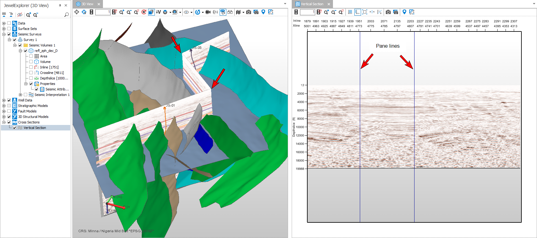
Visualizing a random cross section in the Seismic View. In this example, the random cross section is a 'Vertical Section' consisting of 3 panes, but you can also use a 'Plane Section', as long as it is vertical (0 deg. inclination) click to enlarge
To display a random cross section in the Seismic View or 3D View
You need to have a Vertical Section, Plane Section or Surface Parallel Section (3D View only) available in the Cross Sections folder in the JewelExplorer. See Using cross sections for how to create one.
- Open a Seismic View or 3D View (Workspace > Views).
- In the JewelExplorer, under the Cross Sections folder, select a cross section (Seismic View supports vertical cross sections only).
- For 3D View only - Activate the cross-section's 'object visibility control'. To do this, either double-click on the cross-section in the 3D View, or (in the JewelExplorer) open the cross-section's context menu and select 'Object visibility control'. All objects that can be displayed on the cross-section are indicated with a blue checkbox in the JewelExplorer.
- Under the Seismic Volume item in the JewelExplorer, select a Seismic Attribute. Only one attribute can be selected at the time. If you have more attributes in the same seismic volume, the selection works as a radio button. For the 3D View, the associated seismic volume is
- The view now displays the seismic attribute along the chosen random cross section. In the Seismic View, the name at the top of the view has switched to the name of the (selected) random cross section.